★★★★★
Applied at work
“I went straight to the BLDC firmware section and applied what I learned at work immediately.”
HARDWARE + FIRMWARE. ONE COMPLETE PROJECT.
Design the circuit and PCB. Write the STM32 firmware. Tune a PI speed controller on real hardware. Learn the essential theory and put it to work in one complete embedded project.
Enrollment is open
At launch: 63 lessons · 13h 42m.
The remaining project lessons arrive on November 15, 2026, for approximately 20 hours in total.
Lifetime access · One-time purchase.
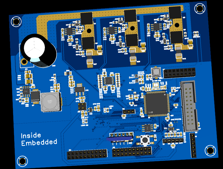
WHAT YOU WILL BE ABLE TO DO
These outcomes cover both releases. Start with the foundations and STM32 register-level labs at launch, then complete the controller project on November 15, 2026.
Applied at work
“I went straight to the BLDC firmware section and applied what I learned at work immediately.”
Understanding the MCU
“Working directly with registers and the datasheet helped me understand the MCU much more deeply.”
Motor control in practice
“The explanations and practical exercises were well structured. The course helped me understand motor control from a practical perspective.”
Theory and practice
“This course helped me decide to pursue a career in power conversion and control. It teaches both theory and practice.”
Connecting hardware and software
“I finally have a clearer understanding of what ‘embedded’ means. The detailed hardware and software explanations really helped.”
A project from start to finish
“Following a project from beginning to end is exactly what I was looking for. I’m really enjoying the course.”
A relevant engineering project
“I wanted an automotive project. Here I learned BLDC control as well as inverter and buck-converter circuit design.”
From theory to firmware
“Buck-converter and inverter design had seemed difficult. I appreciated learning about BLDC motors, from the theory to driving them with firmware.”
Translated excerpts from reviews of the Korean course on Inflearn.
CONNECT WHAT YOU ALREADY KNOW
A job often covers just one part of development. Circuit and STM32 lessons give you useful pieces. Here, you connect them in one motor-control project. You learn why each design decision matters and put it into practice.
THE DEVELOPMENT PROCESS
Follow each engineering decision from the first requirement to the measured motor response.
Course roadmap: foundations and STM32 register-level labs at launch, followed by the remaining controller-project lessons on November 15, 2026.
01Requirements
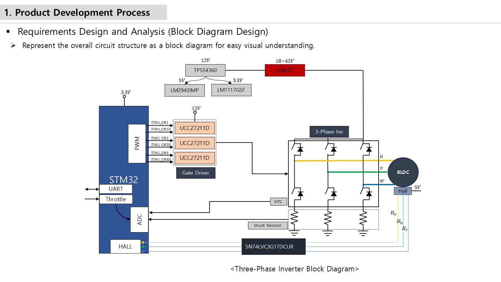
Define requirements, draw the system block diagram and establish the hardware and software interface before designing the controller.
02Circuit design
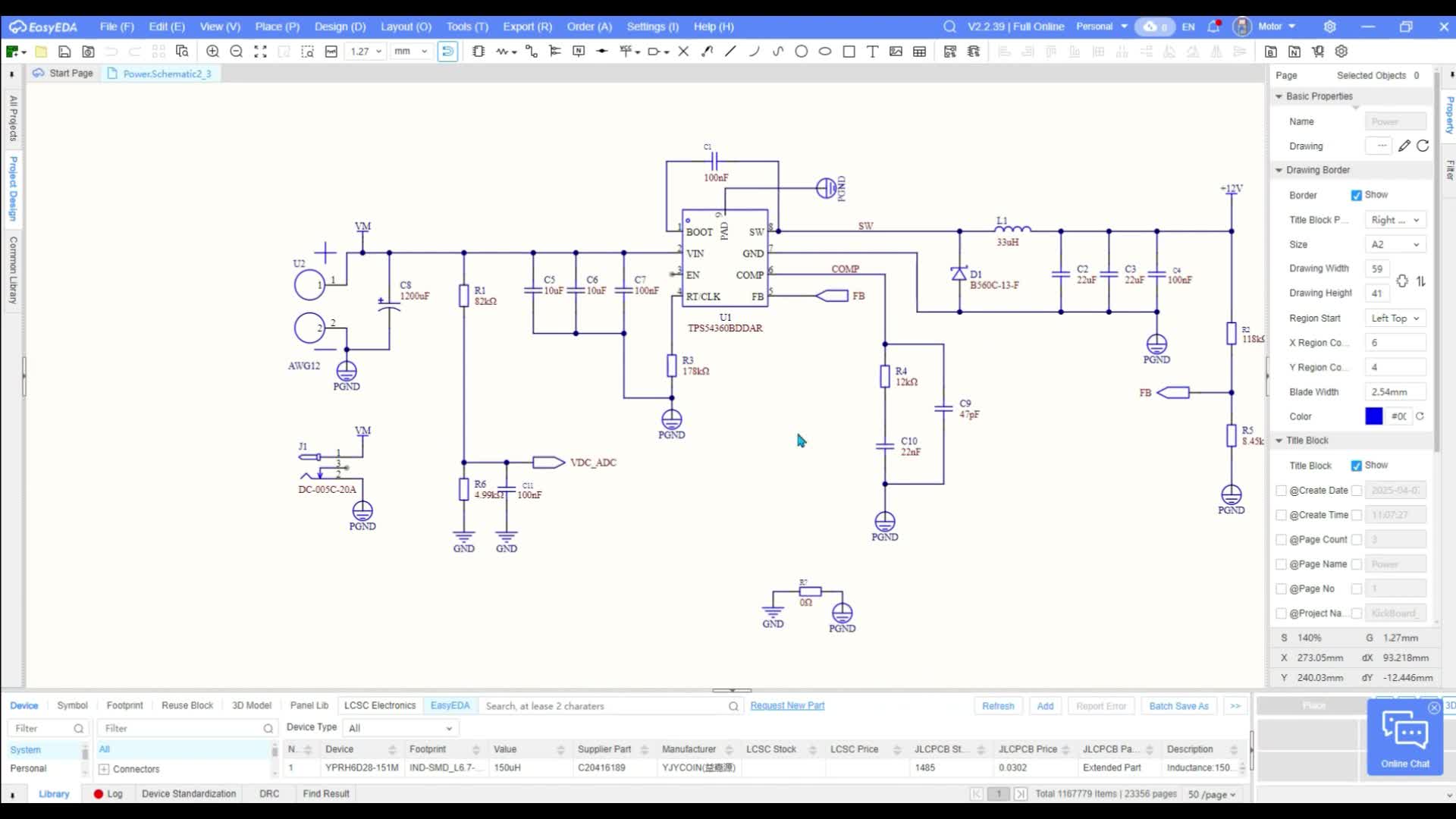
Select the MCU, power supply, MOSFETs, gate drivers and sensing circuits for a 36V / 350W inverter. Build the schematic in EasyEDA.
03PCB design
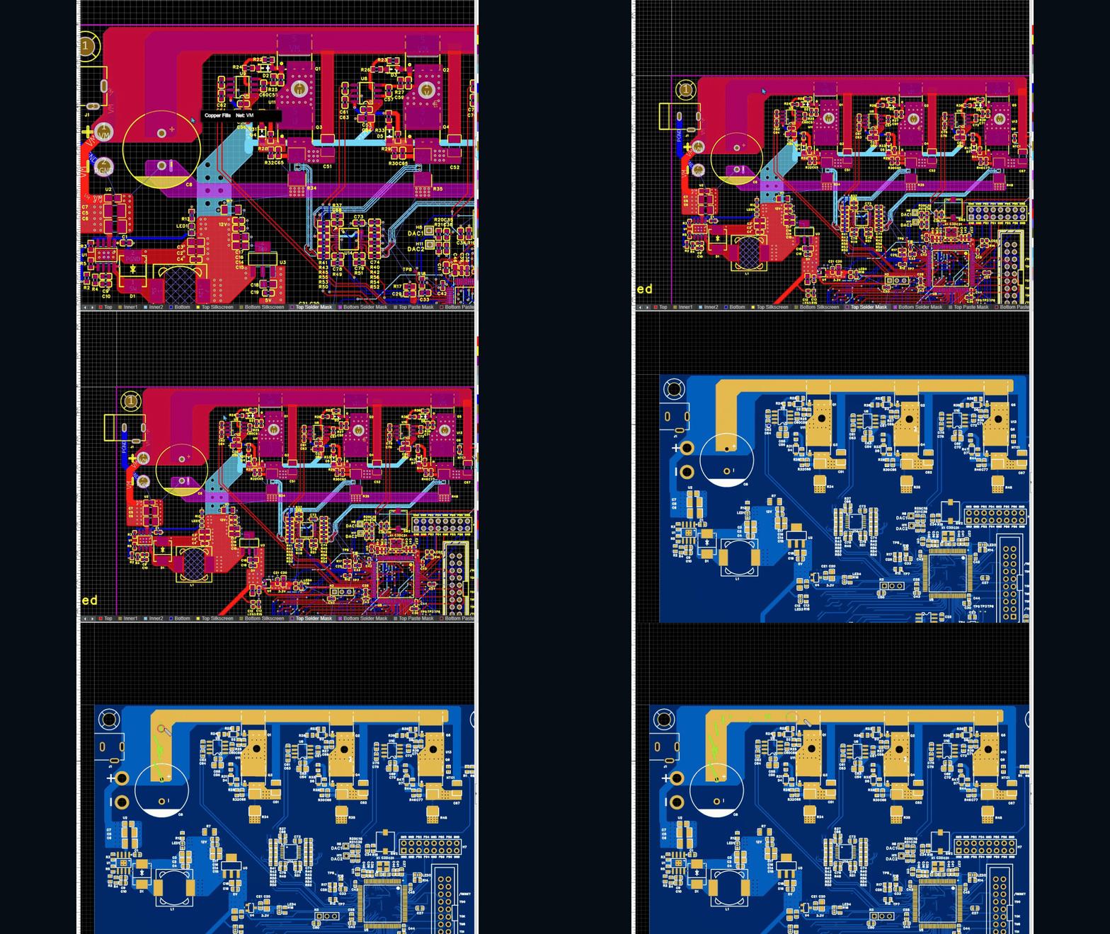
Lay out a 4-layer PCB: power-stage placement, high-current paths, sensitive signals, grounding and return currents.
04STM32 firmware
Configure STM32F767 peripherals directly in C using the reference manual. Connect Hall feedback, commutation and PWM in working firmware.
// Hall inputs: EXTI0, EXTI1, EXTI202EXTI->IMR |= (1<<0) | (1<<1) | (1<<2);03EXTI->RTSR |= (1<<0) | (1<<1) | (1<<2);04EXTI->FTSR |= (1<<0) | (1<<1) | (1<<2);05 06// Enable EXTI interrupts in the NVIC07NVIC_EnableIRQ(EXTI0_IRQn);08NVIC_EnableIRQ(EXTI1_IRQn);09NVIC_EnableIRQ(EXTI2_IRQn);05PI speed control
Measure motor speed, implement the PI controller and tune its gains. Compare target RPM with measured RPM on a compact BLDC motor.
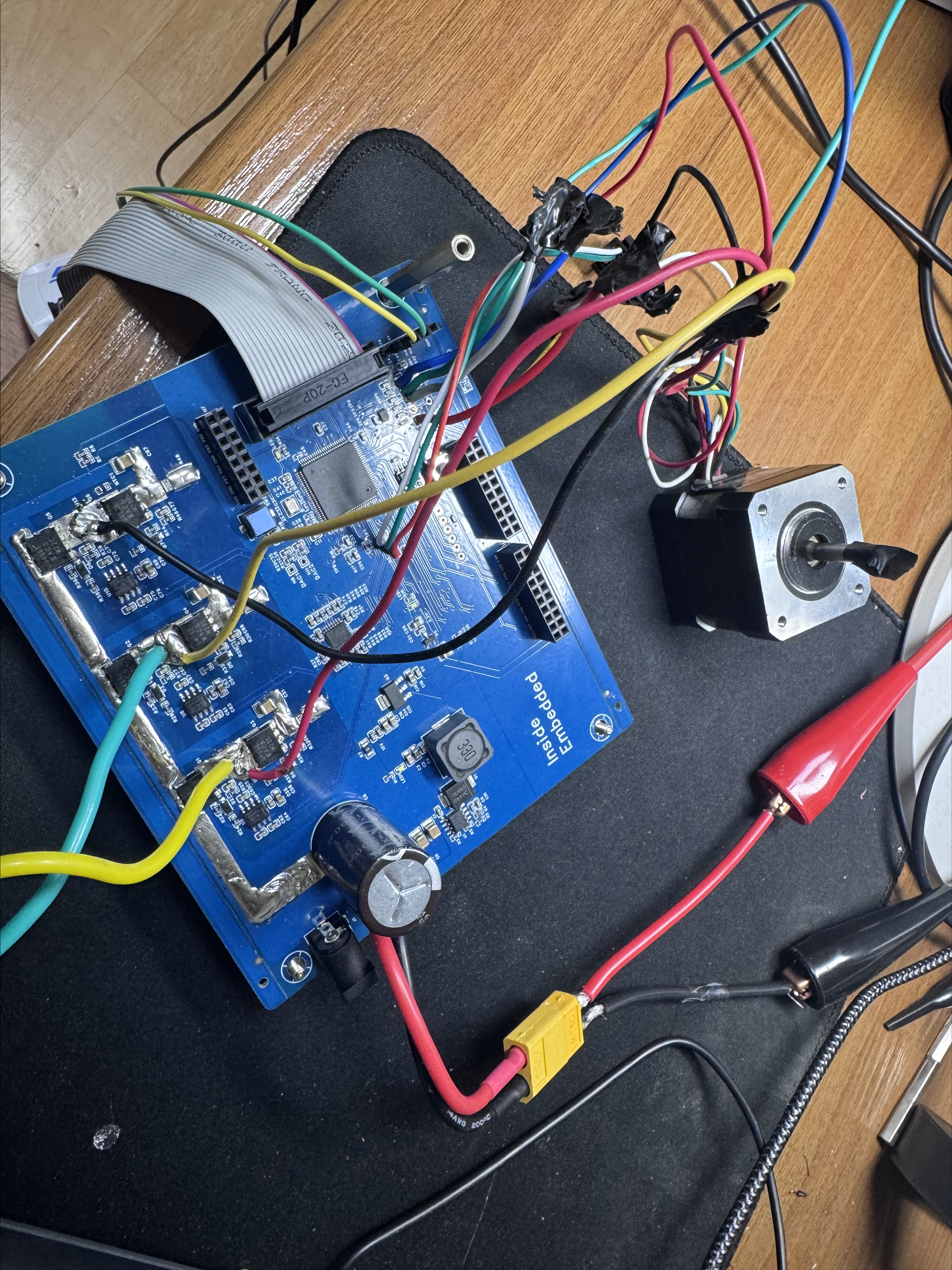
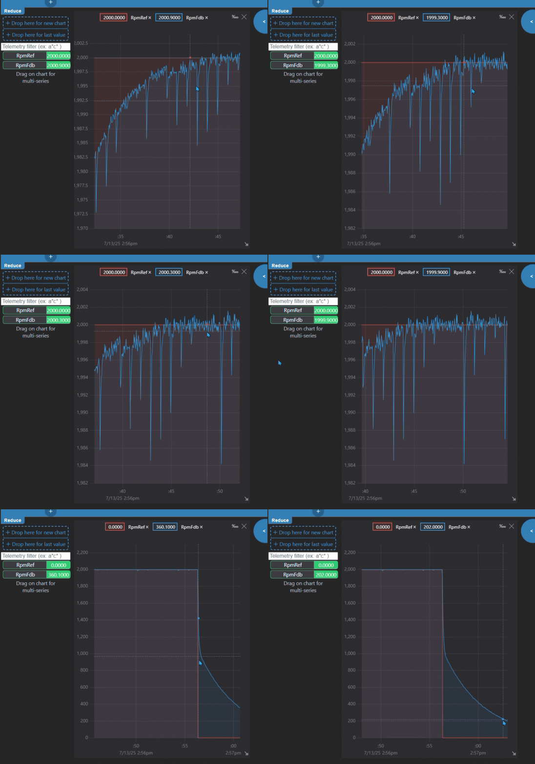
STM32 register-level labs are included at launch. The EasyEDA, motor-control firmware and PI project lessons shown here follow on November 15, 2026. Software screenshots are taken from the course recordings.
TAKE A LOOK INSIDE
See how we work through the theory, circuit design and STM32 code. Choose any sample. No account needed.
WHAT YOU WILL LEARN
Circuit fundamentals, motors and control, inverter design, PCB principles, and 10 STM32 register-level labs.
EasyEDA schematic and PCB practice, BLDC firmware, and PI speed control.
The second release is included in your early-bird purchase at no additional charge. Total running time is expected to be approximately 20 hours. Enrollment is open.
Modules 1 through 5 are included at launch. Modules 6 through 8 are scheduled for November 15, 2026. English audio and English captions are included for all 63 launch lessons. Modules 1 through 5 list the individual video lessons. Modules 6 through 8 show the planned topics.
BEFORE YOU ENROLL
For comfortable study, we recommend 8 GB RAM or more, an SSD and a 1920 × 1080 display. These are course recommendations, not tested minimum specifications. Check the current tool requirements for your operating system and processor before installing.
Both releases are included with course access. The remaining files accompany modules 6 through 8, scheduled for November 15, 2026. The STM32 example archive contains the same eight examples offered as free resources.
The follow-up release includes Gerber files, a JLCPCB fabrication guide and a BOM for making your own board. Wait for those files before ordering parts. A physical kit is not included in the course price.
Budget separately for the PCB and components, a compatible BLDC motor and power supply, an ST-Link programmer, a UART adapter, connectors and wiring. Check the hardware guide before ordering parts.
The main design is a 36V / 350W three-phase inverter. The PI exercise uses a compact 24V BLDC motor. International kit sales and shipping are not currently offered on this site.
You do not need an engineering degree. You should be comfortable with basic C programming and circuit theory. That foundation is enough to follow the course and work through the exercises.
If both subjects are entirely new to you, this course will be challenging. Start with the fundamentals before taking on a complete motor controller. You can try the free STM32 materials first.
Prior motor-control experience is helpful, but it is not a prerequisite.
This is a motor-controller design course. You will connect circuit design, PCB layout, firmware and control on the same piece of hardware.
A good fit if you write firmware and want to understand the circuit you drive, or you design hardware and want to know what the firmware needs from it.
YOUR INSTRUCTOR
Practicing motor-control engineer & educator
Hardware. Firmware. Control.
Connected by engineering practice.
I develop motor and inverter systems for vehicle electrification. My work spans circuit and PCB design, firmware, control algorithms, and validation on the bench and in vehicles.
My work has included collaboration with global automotive manufacturers. I teach as Polezero, sharing the reasoning behind real circuits, firmware and motor-control systems.
I also teach embedded systems and motor control in Korea through my Korean-language courses on Inflearn.
Across my Korean-language courses on Inflearn.
As of October 13, 2026. View my Inflearn profile
Polezero · English engineering lessons
BEFORE YOU BEGIN
The YouTube lessons explain one concept at a time. This course follows one board from the first requirement to a measured speed response: parts, schematic, 4-layer layout, firmware and tuning, in order. You also get the lecture PDFs. Course Q&A is open to everyone, and I answer the questions there myself. With the November 15 release, the course adds the motor-control source code, schematics, a BOM, Gerber files and a JLCPCB guide.
The launch release contains 63 video lessons, totaling approximately 13 hours 42 minutes. Modules 1 through 5 cover circuit fundamentals, motors and control, inverter design, PCB principles, and 10 STM32 register-level labs. It also includes two PDFs totaling 409 pages and an archive of eight STM32 examples already offered as free resources. English audio and English captions are included for all 63 launch lessons. Enrollment is open.
Modules 6 through 8 are scheduled for November 15, 2026: EasyEDA schematic and PCB practice, BLDC firmware, and PI speed control. The complete course is expected to total approximately 20 hours. Both releases and their included materials are covered by the early-bird price.
Hardware is purchased separately. A BOM, schematics, PCB Gerber files and a JLCPCB fabrication guide arrive with the follow-up release so you can make your own board. Wait for the hardware guide and check compatible motors, power supplies, programmers, wiring and accessories before purchasing parts. A physical kit is not included.
Yes. The PI exercise uses a compact 24V BLDC motor. The main hardware design project is a 36V / 350W three-phase inverter.
The early-bird price is a one-time payment of $245 before applicable taxes. It ends on November 15, 2026 at 23:59 UTC; after that, the course is $350. It includes 63 lessons totaling approximately 13 hours 42 minutes at launch, the remaining project lessons scheduled for November 15, 2026, and lifetime access to the complete course. The full course is expected to total approximately 20 hours. No additional payment is required for the second release. Hardware is purchased separately.
ASK BEFORE YOU ENROLL
Ask about the course, prerequisites or hardware. Approved questions and instructor replies are visible to everyone, so you can check what has already been answered.
I have education in mechanical engineering, and have thought of taking this course due to poor job market. I was wondering if there are prerequisites to this BLDC Motor Control course? We had Circuits 1 as part of my education. And I have done some programming in Matlab/ Simulink.
Hi, thanks for asking. Circuits 1 gives you a useful starting point. A basic understanding of circuit theory and electronics will make the course easier to follow, but you don't need to have designed a motor controller before.
I start with the components themselves: resistors, capacitors, inductors, diodes, BJTs and MOSFETs. The course then covers power-supply circuits and works through the controller hardware in detail, including MCU peripheral circuits, a buck converter and a three-phase inverter. So there are explanations of the parts and circuits before we move into the full controller project.
For the STM32 lessons, you'll also need basic C programming. Your MATLAB/Simulink experience is useful, but the firmware is written in C, so I'd suggest reviewing the basic syntax if you haven't used it before.
If you get stuck on a circuit or a piece of code, please ask me here or by email. I'll be happy to explain it in more detail. You may need to revisit a few fundamentals along the way, but you already have some relevant background to build on. The free resistor and buck-converter previews on this page are a good way to see whether the explanations suit you.
A course purchase is not required to ask.